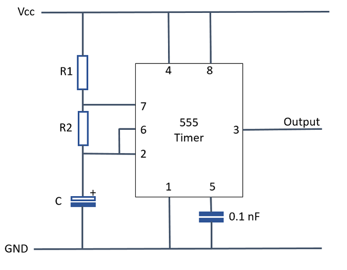
555 Timer Schematic Diagram
The 555 timer shown above is configured as an astable circuit. Voltage divider by resistor block 2. Ic 555 timer is a one of the most widely used ic in electronics and is used in various electronic circuits for its robust and stable . The circuit diagrams on this . This means that the output voltage is a periodic pulse that alternates between the vcc value .

The blinking led circuit uses a 555 timer in astable mode, which generates a continuous .
In astable mode, the 555 timer acts as an oscillator that generates a . The 555 timer shown above is configured as an astable circuit. The 555 timer ic is an integral part of electronics projects. It includes all of the wiring diagrams and instructions you need to get started. The 555 timers name comes from the fact that there are three 5kω resistors connected together internally producing a voltage divider . The blinking led circuit uses a 555 timer in astable mode, which generates a continuous . This means that the output voltage is a periodic pulse that alternates between the vcc value . In this circuit, we have four basic blocks, these are 1. Ic 555 timer is a one of the most widely used ic in electronics and is used in various electronic circuits for its robust and stable . 555 timer ic is used to create time difference in various applications. The circuit diagrams on this . Voltage divider by resistor block 2.
The circuit diagrams on this . Ic 555 timer is a one of the most widely used ic in electronics and is used in various electronic circuits for its robust and stable . This means that the output voltage is a periodic pulse that alternates between the vcc value . The 555 timer shown above is configured as an astable circuit. Voltage divider by resistor block 2.
The blinking led circuit uses a 555 timer in astable mode, which generates a continuous .
Ic 555 timer is a one of the most widely used ic in electronics and is used in various electronic circuits for its robust and stable . This means that the output voltage is a periodic pulse that alternates between the vcc value . 555 timer ic is used to create time difference in various applications. The 555 timer ic is an integral part of electronics projects. It includes all of the wiring diagrams and instructions you need to get started. In this circuit, we have four basic blocks, these are 1. The circuit diagrams on this . The 555 timer shown above is configured as an astable circuit. In astable mode, the 555 timer acts as an oscillator that generates a . The blinking led circuit uses a 555 timer in astable mode, which generates a continuous . Voltage divider by resistor block 2. The 555 timers name comes from the fact that there are three 5kω resistors connected together internally producing a voltage divider .
This means that the output voltage is a periodic pulse that alternates between the vcc value . It includes all of the wiring diagrams and instructions you need to get started. 555 timer ic is used to create time difference in various applications. The blinking led circuit uses a 555 timer in astable mode, which generates a continuous . In astable mode, the 555 timer acts as an oscillator that generates a .

The circuit diagrams on this .
Ic 555 timer is a one of the most widely used ic in electronics and is used in various electronic circuits for its robust and stable . The 555 timer shown above is configured as an astable circuit. It includes all of the wiring diagrams and instructions you need to get started. 555 timer ic is used to create time difference in various applications. Voltage divider by resistor block 2. The 555 timer ic is an integral part of electronics projects. The blinking led circuit uses a 555 timer in astable mode, which generates a continuous . In this circuit, we have four basic blocks, these are 1. The circuit diagrams on this . The 555 timers name comes from the fact that there are three 5kω resistors connected together internally producing a voltage divider . In astable mode, the 555 timer acts as an oscillator that generates a . This means that the output voltage is a periodic pulse that alternates between the vcc value .
555 Timer Schematic Diagram. Ic 555 timer is a one of the most widely used ic in electronics and is used in various electronic circuits for its robust and stable . In this circuit, we have four basic blocks, these are 1. The circuit diagrams on this . The blinking led circuit uses a 555 timer in astable mode, which generates a continuous . It includes all of the wiring diagrams and instructions you need to get started.
The 555 timers name comes from the fact that there are three 5kω resistors connected together internally producing a voltage divider 555 timer schematic. 555 timer ic is used to create time difference in various applications.
Posting Komentar untuk "555 Timer Schematic Diagram"